
Timelapse+ VIEW
Welcome! This is the official documentation for the VIEW Intervalometer by Timelapse+. You can scroll through the entire document or click on the links on the left to jump to a specific section. If you find errors or if parts are confusing, contact me via https://www.timelapseplus.com/contact or make the correction yourself and send a pull request with github here: https://github.com/timelapseplus/VIEW-documentation
Este documento tambien existe en Español: https://es.view.tl
This documentation is updated for VIEW firmware v1.8.X. If you are using an older version, make sure to upgrade: https://docs.view.tl/#firmware-update
This document is formatted for printing, and can be printed as a PDF for a portable copy. It can be found online at https://docs.view.tl
Overview and Operation
Power and Buttons
Power On
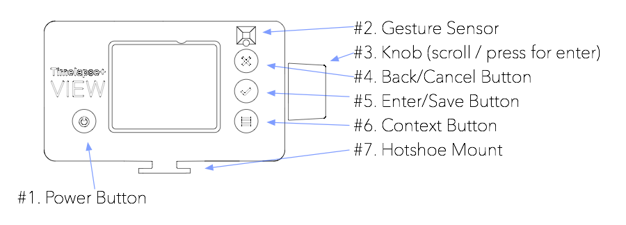
To power on the VIEW, press and hold the Power button (#1) for 3 seconds. It will flash shortly after being pressed and can be released once it’s lit solid, indicating that it’s booting. The VIEW logo will appear on the screen shortly thereafter. It takes a little over a minutes to fully boot.
Power Off
To power off the VIEW, press and hold the Power button (#1) for 2 seconds. A confirmation prompt will appear on the screen. Turn the knob to select “Yes” and
press the knob or the Enter button (#5) to power off.
If the VIEW is not responsive, it can be forced off by pressing holding the Power button (#1) for 15 seconds. It can then be booted normally by pressing the Power button again for 2 seconds.
Operation
The user interface for the VIEW is a menu based system designed to be simple to operate outdoors and with gloves. For that reason, there’s no touchscreen, but rather simple buttons and a knob for scrolling through options. Use the knob to scroll up and down through the menus. To select open or select the highlighted menu item, press the knob or the Enter button (#5). To go back or cancel, press the Cancel button (#4). Some screens use the Context (#6) button for additional options indicated on the screen.
Gesture Sensor
The Gesture Sensor (#2) while a time-lapse is running and the screen goes blank. Wave your hand across the front to activate, then wave to the right to preview the current/last time-lapse, or to the left to cancel. While the preview is playing, wave to the right to skip ahead 10 seconds. If the gesture sensor does not respond as expected, try calibrating it via Settings->UI Preferences->Calibrate Gesture.
Ports and Connections
Charging
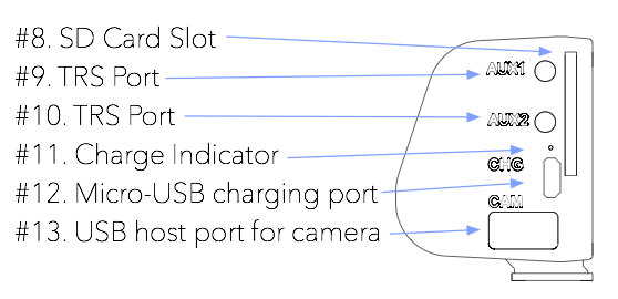
To charge the VIEW, connect a Micro-B USB cable from a USB power supply (USB charger, battery pack or computer) to the charging port (#12) on the VIEW. When connected the Charge Indicator (#11) will illuminate red, blinking while charging, and steady when full. This light can be disabled in Settings->Charge Indicator. Note that the battery indicator in the VIEW will prematurely show a low battery, and if charging a completely dead battery, it can take some time before progress becomes visible. It can be charged/powered while running.
Auxiliary Ports
The VIEW includes two 2.5mm TRS auxiliary ports (#9, #10) for motion sync, shutter cable triggering and external integrations. Currently only AUX2 is used by the firmware. It will send a pulse to trigger motion systems to move after each shot during a time-lapse (no setup necessary for this), or it can be used as an external trigger for the interval when the time-lapse interval is set to “External”. See https://docs.view.tl/#motion-control for more.
SD Card
The SD card slot (#8) provides a convenient way to save images (https://docs.view.tl/#sony-alpha-usb), get data from the VIEW, or update firmware (https://docs.view.tl/#update-via-sd-card).
The VIEW supports all current SD card types and capacities, but internally it uses a Class 10 controller, so the newest UHS II cards will not offer a speed improvement over a Class 10 card. Cards can be formatted with the camera or on a computer as FAT/EXFAT (MSDOS).
USB Host
The VIEW includes a full-size USB host port (#13) for connecting the camera. This port also supports USB hubs for connecting multiple devices (right now it can also communicate with the DP NMX and eMotimo ST4 via USB, and multiple cameras are also supported.
Hooking up the camera
Hotshoe Mount
The VIEW can be conveniently connected to the top of the camera by sliding it on the camera’s hotshoe. This also provides PC-sync feedback for ensuring proper shoot-move-shoot operation when used with motion control, however, if you’re not using motion control you can mount the VIEW anywhere without affecting the performance.
USB Connection
Connect the appropriate USB cable for your camera from the Host Port (#13) to your camera’s USB port. It’s best to have the camera powered on before connecting, as there seems to be an occasional timing issue causing the camera to not properly connect if powered on while connected. If the camera doesn’t seem to connect, unplug the USB and reconnect. Sony cameras can be quite flaky – if you’re having trouble, try removing the battery from the camera, powering it back on, and then plugging in the USB to the VIEW again.
Some cameras need to be set to “PC Connect” or “PTP Mode” in order for USB to function properly. Also, some Canon cameras with WiFi (like the 6D) require WiFi to be disabled for USB control to work. See https://docs.view.tl/#camera-specific-notes for more.
Only the USB cable is needed for full ramping support. No other connections are necessary.
Time-lapse Setup
Start by connecting the camera via USB as described in the previous section. This will enable the Time-lapse menu (the first item on the main screen). Press the knob or enter button to select. You’ll then see the options listed in this section.
Quick Setup for the first test
For your first automatic ramping test, I recommend to start with the following configuration:
| Setting | Recommended Value |
|---|---|
| Exposure | Just setup the camera for the current scene before hand and skip this step |
| Timelapse Mode | Auto Ramping |
| Interval Mode | Auto Variable |
| Day Interval | 8 seconds |
| Night Interval | 40 Seconds |
| Destination | Camera 1 |
I recommend starting an hour before sunset, setting the camera at the lowest ISO, a moderately wide aperture (e.g., f/2.8) and then setting the shutter speed to whatever is needed for a good exposure (maybe 1/3200). Make sure it’s not overexposed!
Then, let it run at least 3 hours after sunset to get a good length and transition. Or, if you have external power for the camera, go all night until sunrise!
To stop the time-lapse, press the menu (lower right) button while in the time-lapse status screen and then select “Stop Time-lapse”.
Once the time-lapse is complete, check out the post-processing section.
1This setting only appears if there is an SD card in the VIEW. For older Sony cameras connected via USB, you’ll need to set this to ‘SD Card’ and make sure an SD card is in the VIEW. For other cameras, performance is best when saving directly to the camera. Sony can save to the camera when connected via WiFi instead of USB (see camera-specific notes for more).
Time-lapse options are described below
Exposure
Puts the camera in liveview mode for adjusting the exposure and focus. Press the menu (lower-right) button to cycle the selection between the settings shown below the image. Turn the knob to increase/decrease selected setting.
Timelapse Mode
| Option | Description |
|---|---|
| Fixed | This is for a basic time-lapse where the exposure and interval are constant throughout |
| Auto Ramping | In this mode the VIEW will automatically adjust the exposure to match changing light conditions |
For short time-lapse clips during the day or night where the exposure and interval are constant, choose Fixed.
For sunsets, sunrises, day to night, night to day, and day to night to day, choose Auto Ramping. This will also enable the Auto Interval options for interval ramping between day and night.
Primary Camera
This option is only shown when more than one camera is connected to the VIEW. The primary camera selection defines the camera used for setup and liveview, the status thumbnail, and the exposure tracking. The settings from the primary camera are copied to all additional cameras connected, and they are triggered in sync. This is nice for panoramas, as well as a wide view and a telephoto view for post-processing transitions. In the case of wide and telephoto, make the wide view the primary for better exposure tracking.
Interval Mode
This option is only shown when Timelapse Mode is set to 'Auto Ramping’
| Option | Description |
|---|---|
| Fixed Length | This maintains the same interval through out the time-lapse and will limit the maximum shutter speed to fit within it |
| Auto Variable | This mode will automatically ramp between a Day Interval and a Night Interval and allows for longer shutter speeds at night |
| External AUX2 | Use this for synchronization with a motion system where the motion’s camera trigger is connected to AUX2 and defines the interval (see https://docs.view.tl/#external-trigger) |
Interval
This option is only shown when Timelapse Mode is set to 'Fixed’ or Interval Mode is set to 'Fixed’
| Option | Description |
|---|---|
| [time in seconds] | Interval length in seconds. This is the time between the start of one frame to the start of the next |
Frames
This option is only shown when Timelapse Mode is set to 'Fixed’. In Auto Ramping mode, the VIEW always runs until stopped.
| Option | Description |
|---|---|
| [number of frames] | Number of exposures to complete before stopping |
Day Interval
This option is only shown when Timelapse Mode is set to 'Auto Ramping’ and Interval Mode is set to 'Auto Variable’
This determines the interval length during daylight, based on the camera’s exposure settings. It will be smoothly ramped to/from the Night Interval as the ambient conditions (and camera exposure) change.
| Option | Description |
|---|---|
| [time in seconds] | Interval length in seconds. This is the time between the start of one frame to the start of the next |
Night Interval
This option is only shown when Timelapse Mode is set to 'Auto Ramping’ and Interval Mode is set to 'Auto Variable’
This determines the interval length during the night, based on the camera’s exposure settings. It will be smoothly ramped to/from the Day Interval as the ambient conditions (and camera exposure) change.
| Option | Description |
|---|---|
| [time in seconds] | Interval length in seconds. This is the time between the start of one frame to the start of the next |
Ramping Options
This option is only shown when Timelapse Mode is set to 'Auto Ramping’.
In this menu, there are a few settings to configuring the limits of auto ramping. Note that these options can limit the range of ramping and thereby cause it to not reach a proper exposure if too limited. For most cameras, a max ISO of 6400 does well, with a lower ISO limit of 100 (best to only use native ISOs, not lower).
The Night Exposure setting defines how much less exposed “night” should be, relative to “day”. For example, a night exposure of -1 (the default), will underexposure a night scene by 1 stop compared to the day. So, if an auto ramp is started during the day, and by night the exposure it too light, a lower night exposure is needed. Or, if the images after sunset are too dark, a higher value should be used. A Night Exposure setting of 0 will keep the day and night perceived luminosity the same.
| Option | Description |
|---|---|
| Maximum ISO | Upper ISO limit for auto ramping |
| Minimum ISO | Lower ISO limit for auto ramping |
| Max Shutter | Longest shutter speed to use during ramping |
| Ramp Params | Which parameters to use for ramping 1 |
| Highlight Protection | When enabled, the VIEW will immediately decrease the exposure by 1/3 stop after each frame where excessive clipping is detected |
| Min Aperture | Minimum aperture to use for ramping, e.g., f2.8 (shown only if Ramp Params includes aperture) |
| Max Aperture | Maximum aperture to use for ramping, e.g., f11 (shown only if Ramp Params includes aperture) |
| Day Lum Target | Target image brightness for day exposure 2 |
| Night Lum Target | Target image brightness for day exposure 2 |
1The “balanced” option tries to move shutter and ISO together, to more gradually increase the shutter speed. The other settings always prioritize the lowest ISO possible.
2When starting during the day, the Day Lum Target is not used – instead, the day brightness is based on the starting frame. Likewise, when starting at night for a sunrise to day, the Night Lum Target is not used either – only the day target.
- Once the transition begins (sunrise or sunset) the VIEW switches between using the luminance of the starting frame as a target exposure and instead uses the Luminance Target of Night or Day, depending on which is approaching. So once you’ve found night/day target values that you like, you don’t have to change them.
- The defaults are to have the Day Target at 0 – meaning that to the VIEW the image seems to have a balanced exposure, and the Night Lum at -1.3, meaning that the exposure is about 1.3 stops less than balanced, giving the appearance of night.
- If you did a night to day and thought the ending day exposure was about a stop too dark, increase the Day Lum Target to +1. Keep in mind, however, it does run a little dark during sunrise to preserve colors and highlights and will brighten some after.
Manual Aperture
This option is only shown when the aperture setting of the lens cannot be read from the camera, such as when using a manual lens or the lens-twist method.
Enter the aperture setting of the lens here to aid in the calculation of absolute exposure values to aid in day/night feathering of interval and exposure compensation.
| Option | Description |
|---|---|
| [aperture] | Aperture value that the lens is set to or locked on (in the case of lens-twist) |
Destination
This option is only shown when an SD card is inserted in the VIEW. Older Sony cameras require that the images be saved to the VIEW’s SD card (https://docs.view.tl/#sony-alpha-usb), but otherwise it is recommended to only save to the camera’s card
| Option | Description |
|---|---|
| Camera | Keep images on the camera’s card. No SD card is needed in the VIEW. This option is recommend for best performance. |
| SD Card | Saves the time-lapse images in their own folder in the root of the SD card, along side the XMP files for Lightroom smoothing. |
START
If you have all the settings entered, select this option to start the time-lapse! While it’s running, press the enter (middle right) button or wave your hand to the right to review the results in process, or press the menu (lower right) button to stop the time-lapse.
To stop the time-lapse, press the menu (lower right) button while in the time-lapse status screen and then select “Stop Time-lapse”.
Smartphone App Control
The VIEW Intervalometer can be controlled and monitored via an app for mobile devices. There’s also a web-app version so that anything with a web browser can access it, although it’s only optimized for mobile-sized screens.
TL+VIEW app for iOS: https://apps.apple.com/us/app/tl-view/id1412185976
And for Android: https://play.google.com/store/apps/details?id=com.timelapseplus.view
Regardless of whether you use the native app or the web interface, there are two methods for connecting to the VIEW from a mobile device: a local WiFi method, and an internet method.
Local WiFi Pros:
- No Internet required, works in remote locations
- Low-latency connections, great with streaming liveview during setup
Local WiFi Cons:
- Only works within WiFi range of the VIEW
- Internet will not function on the mobile device while connected to the VIEW’s WiFi network
Internet Method Pros:
- Access the VIEW from anywhere in the world!
- Mobile device can be connected to the internet as usual
Internet Method Cons:
- The VIEW needs to be within range of a WiFi access point for internet (you could use a mobile hotspot)
- Higher latency so you’ll see some lag with liveview
Connecting via local Wifi

To configure the local WiFi app interface, setup the following on the VIEW:
- Enable WiFi (if it’s not already): Settings->Wireless Setup->Enable Wifi
- Enable Access Point Mode: Settings->Wireless Setup->Enable built-in AP (if this setting is missing it means it’s already enabled)
Then, on the mobile device:
- Connect to the TL+VIEW WiFi access point1
- Open the TL+VIEW app, or use a web browser and go to 10.0.0.1
The name of the built-in access point can be changed under Settings->Wireless Setup->Set built-in AP Name.
1Note: In v1.8 and newer, a password is required. The default is “timelapse+” and it can be viewed/changed in Settings->Wireless Setup->Set built-in AP Password
Connecting via the Internet

To access the VIEW over the internet, setup the following on the VIEW:
- Enable WiFi (if it’s not already): Settings->Wireless Setup->Enable Wifi
- Connect to a nearby access point: Settings->Wireless Setup->Connect to Network
- Enter the password for the network if necessary (make sure it’s entered correctly with the correct case). Use the context button on the lower right to switch between uppercase/lowercase/numbers/symbols. Press the power button on the password screen for more instructions.
- Once the VIEW connects (only the first time), a number will appear on the screen. You’ll need this for step 4 below.
Then, on the mobile device:
- Open the TL+VIEW app or use a web browser and go to https://app.view.tl
- Login or register using your email address.
- Once logged in, if this is your first time, press ‘Add Device’ (if you’ve done this before, you don’t need to again)
- Enter the numbers displayed on the top of the VIEW screen (or find them in Information->Registration & App) – this links your device to your app account
Using the app
The app has 4 sections: CAMERA, INTERVALOMETER, TIME-LAPSE CLIPS, and SETTINGS. To switch between sections, press the menu icon on the upper left of the app, or swipe right from the left edge of the screen to open the menu.
CAMERA
This section allows manual control of the camera for taking single images, changing settings, and using liveview. This can function as a remote trigger for the camera.
Beneath the image box at the top, there is a round LV button on the right – press this to enable the liveview display. In the center is a blue button which will capture a single image. On the left is a 2 second timer – the camera will capture an image after 2 seconds.
Further down, there are tabs to switch between different controls: - Exposure - change the shutter, aperture and ISO on the camera - Focus - move the focus position manually (if supported) - Motion - move various motion axes (if supported and connected)
INTERVALOMETER
In this section you can setup, start, and monitor a time-lapse on the VIEW. Note that once a time-lapse is started from the app, the app does not need to remain connected; it runs independantly on the VIEW.
The parameters are the same as found on the VIEW itself – see http://docs.view.tl/#time-lapse-setup for details on each parameter.
There are a few things the app has in addition to the VIEW:
- Keyframe Motion - video demonstration: https://vimeo.com/272661750
- Delayed Start - instead of pressing the start button at the bottom, use the delay button left of it. Then set the delay and it will automatically start after the delay amount (the app can be closed during the wait).
- Scheduled Time-lapse - set Enable Scheduling = 'enabled’ and then select the days of the week and the daily start/stop time.
Additionally, the app also allows changing parameters of a time-lapse that is running, whether it was started via the app or on the VIEW. While a time-lapse is running, this screen will show the status instead of the setup parameters. Some of the parameters shown in the time-lapse screen have a blue box around them. These can be changed while it’s running. Depending on the type of parameter, the change can be made over a series of frames instead of at once. If a parameter on the status screen is outlines in red instead of blue, it means it’s currently applying a change (the change can still be modified if needed).
TIME-LAPSE CLIPS
In this section you can review previous time-lapses capture with the VIEW. If you tap a time-lapse, it will open and can be played back (in low-res).
When a time-lapse is open there is a red button on the right to delete the clip (this deletes the low-res preview on the VIEW – nothing else), and a blue button for copying the settings used from this clip and opening them in the INTERVALOMETER section to create a new time-lapse based on them.
Additionally, if there was a problem with the clip, a copy of the log file can be sent to support to aid in diagnosis of the problem using the link found at the bottom of the screen when viewing a time-lapse clip. You will then receive an email – please reply to that email with a description of the problem.
SETTINGS
The SETTINGS section is somewhat minimal yet, but the following is available:
- Pair a new VIEW device (opens a dialog to enter the pairing number on a new device for linking it to your account)
- Configure Motion - this is available when a compatible motion system is connected and includes settings related to the specific motion system
- Logout – this logs out the current user, in case you need to log back in with a different email or are using a shared system
Firmware Update
The VIEW Intervalometer can be updated on its own – no computer is necessary, just a wifi access point for Internet access.
The firmware is loaded directly from github releases, so you can also browse the available firmware here: github.com/timelapseplus/VIEW/releases/
The current firmware version is displayed on the top line of the screen on the VIEW when a camera is not connected. It can also be found in Information->System Info.
Update via Wifi
This is usually the easiest method, provided a wireless internet connection is available. Note that the VIEW is not able to log into captive portals (such as hotel wifi where you need to log in with a room number), so in that case the SD card method below can be used.
Step 1: Connect the VIEW to the internet
The VIEW must first be connected to the Internet. Follow these to connect to a WiFi access point for Internet access:
- Enable WiFi (if it’s not already): Settings -> Wireless Setup -> Enable Wifi
- Connect to a nearby access point: Settings -> Wireless Setup -> Connect to Network
- Enter the password for the network if necessary (make sure it’s entered correctly with the correct case). Use the context button on the lower right to switch between uppercase/lowercase/numbers/symbols. Press the power button on the password screen for more instructions.
You can ignore any prompts to enter a code – just press the cancel button.
Step 2: Update firmware
Next, navigate to Settings -> Software Version. If it’s successfully connected to the Internet, it will delay a few seconds while it retreives the latest firmware information. If it’s not connected to the Internet, it will only show the previously installed versions (this is so you can always roll back, even when there’s no Internet available). If it just loads the installed versions, return to step 1 above and verify the network password is correct or try a different access point.
Once the Software Version menu has loaded, you can select the firmware version to install. Press the power button to read the release notes for the selected version. Press the knob or the enter button to install the selected version. Updating to the most recent version is always recommended.
The installation will take between 5 and 30 minutes, depending on the connection quality. Upon success, the system wil reload, displaying the boot splash screen. If it fails, it will return to the Software Versions menu (better feedback in the UI will be added for this in the future).
Firmware updates will either fail or succeed – it won’t get stuck in a corrupted state. That said, it’s possible for it to hang when downloading if there’s a network interruption (working on fixing this). If after 15 minutes or so the VIEW still says it’s downloading the firmware, it may need a force-restart. Hold the power button for fifteen seconds to power down, then 2 seconds to boot it back up. It will load the old firmware version, and then you can try again to update. A future update will provide better error handling & reporting and progress reporting (like a progress bar for the download).
Update via SD Card
- Using a computer with internet access, download the latest firmware source code zip file from the releases page here: github.com/timelapseplus/VIEW/releases/
- Copy the downloaded zip file to the root folder of an SD card (it doesn’t need to be empty, it just needs enough space for the zip file). Do not rename the zip file – the name is used by the VIEW for recognizing the firmware and version.
- Insert the SD card with the zip file into the VIEW.
- On the VIEW, go to Settings->Software Version->Install from SD card to begin installation. If there is more than one firmware zip file on the SD card, it will automatically select the most recent version.
Recovery Method
If for some reason the system is corrupted and the VIEW will not boot past the splash screen, the system can likely be restored with the following steps:
download a firmware zip file from github.com/timelapseplus/VIEW/releases/ and save it to the root folder of an SD card
force power off the VIEW by holding the power button for 15 seconds until the red light turns off
insert the SD card with the firmware file into the VIEW
power on the VIEW by pressing the power button for two seconds
within a couple seconds of power on, press and hold the enter (middle right) button for about 20 seconds until the splash screen appears
At the bottom of the screen it should say “Updating…”. After a few minutes, it should be restored.
Camera-Specific Notes
This section includes notes and issues specific to certain camera bodies. Camera-specific issues will be corrected in firmware when possible and removed from this section once resolved.
Notes for all cameras
- Manual mode
- A native ISO setting (not Auto)
- Save as RAW (not RAW+JPEG)
- Disable any long exposure noise reduction
- Focus should be manual or back-button (if the shutter button activates focus it can cause issues)
- It’s best to disable image stabilization
Sony Alpha (USB)
There are two groups of Sony cameras, the 1st and second generation ones and the new 3rd generation cameras (A7rIII, A9, A7III). The 3rd generation cameras allow the RAW images to be kept on the camera allowing much faster performance via USB.
There have been reports that not all micro-USB cables work with Sony cameras, so if it fails to connect, try a different USB cable. The new USB-C cables are a much more secure option on the cameras that support it.
Some Sony cameras allow charging while in use via the USB port. If this is enabled, the VIEW’s battery will drain rather quickly, so external power to the VIEW is recommended. The VIEW cannot supply enough power to the camera to charge the battery during operation, but it will greatly extend the battery life. So if you have a full battery in the camera and have a USB power source connected to the VIEW (like a cell phone charging pack), the whole setup should last at least 12 hours before the camera’s battery slowly drains (varies depending on camera and interval).
1st and 2nd generation Sony Alphas
This includes the A6000, A6300, A6500, A7, A7r, A7s, A7rII, A7sII, A7II.
1st and 2nd generation Sony cameras can work well, but there are several things that the VIEW currently does not enforce but must be set in the camera for it to work.
Setup the following on the camera:
- USB Mode set to ‘PC Remote’
- RAW files (not JPEG or RAW+JPEG)
- Manual mode, in a native ISO (not the ISO numbers with a line over them, nor auto ISO)
- Focus set to manual (the back button still works for autofocus, but this prevents it from trying to focus on every shot)
- Make sure long exposure noise reduction is disabled
On the VIEW in the time-lapse setup menu, the Destination must be set to SD card. Insert an SD card into the VIEW for this option to appear. This is required because a limitation in the Sony firmware prevents it from being able to save to the camera’s card while it’s connected via USB.
The Sony A7RII needs longer intervals due to the large file size if using USB. 8 seconds should be good – shorter might be possible. Other Sony cameras seem to do ok at 4-5 seconds for a minimum interval.
3rd and 4th generation Sony Alphas
This includes the A7rIV (4th gen), A7rIII, A9 and A7III. On these cameras, USB is the recommend connection method over wifi.
It is possible to save the RAW images to the camera to improve interval times. These cameras now also support focus ramping with the VIEW as well.
Setup the following on the camera (3rd gen):
- RAW + smallest JPEG possible
- USB Mode set to 'PC Remote’
- In PC Remote Settings, set Still Img Save Dest to 'PC+Camera’, and set RAW+J PC Save Img to 'JPEG’
- Manual mode, in a native ISO (not the ISO numbers with a line over them, nor auto ISO)
- Focus set to manual (the back button still works for autofocus, but this prevents it from trying to focus on every shot)
- Make sure long exposure noise reduction is disabled
Video for 3rd gen setup: https://vimeo.com/297232264 Video for 4th gen setup: https://vimeo.com/386651214
Focus ramping with Sony: https://vimeo.com/387080128
Sony Alpha (Wifi)
The Wifi interface allows the 1st and 2nd generation cameras to save the the camera’s memory card, but in general is not as reliable as USB, which is now recommended since the new camera driver (in VIEW firmware v1.8).
To connect the camera via wifi:
- On the camera, open the “Smart Remote Control” app (must be updated to the latest version to work!).
- The camera will display the wifi information. Press the “delete” button on the camera to display the password.
- Connect the VIEW’s wifi (Settings->Wireless Setup->Connect to Network) to the camera’s, using the password shown on the camera screen.
- The VIEW should show that the camera is connected within a few seconds, and the camera will enable liveview again.
- IMPORTANT: press the menu button on the camera and make sure it’s set to RAW+JPEG (small). The setting here does not follow what the camera was previously set to, and RAW only is not an option, but RAW+JPEG (small) works.
When using the wifi interface, the time-lapse Destination setting must be set to “Camera”. Afterward, you can get the XMPs via the Time-lapse Clips menu.
At present, a limitation with Sony wifi is that since the wifi interface on the VIEW is used for the camera, it’s not possible to use the remote app. It might be possible in the future firmware release to have two wifi interfaces to work around this.
Nikon
Many Nikon cameras have the option of whether liveview displays the simulated exposure or not. If you are using the exposure menu or liveview via the app, you’ll want to make sure the liveview display shows the exposure. On the D800, this is toggled by a button on the lower-left. On the D5100 and possible other older/lower-end models, it is not possible to simulate exposure with liveview. In this case, a test photo can be used via the smartphone app.
Note: some VIEW devices would not connect to the Nikon D800/D800E until firmware version v1.7.5. Updating to v1.7.5 or newer will fix this.
Panasonic
Make sure the USB mode on the camera is set to PC Tether (for the GH3 & GH4 set it to “Remote Control (PTP)”), in manual mode, RAW, and single-shot burst mode. For the GH5, GH5S, and G9, firmware v1.8-beta23 or newer is required for the VIEW.
Setup video: https://vimeo.com/349567517
Fuji X
Note: Fuji support requires v1.8-beta13 or newer firmware on the VIEW. Make sure the USB mode on the camera is set to PC Auto. ISO should be manually set to 200 or higher (160 or higher for the X-T3).
Some Fuji cameras allow charging while in use via the USB port. In this case, the VIEW’s battery will drain rather quickly, so external power to the VIEW is recommended. When testing with a fully charged VIEW and full battery in an X-T2, I was able to get 1200 frames over 4 hours before the VIEW ran out of power (the camera still had battery since it was being charged by the VIEW). The VIEW cannot supply enough power to the camera to charge the battery during operation, but it will greatly extend the battery life. So if you have a full battery in the camera and have a USB power source connected to the VIEW (like a cell phone charging pack), the whole setup should last at least 12 hours before the camera’s battery slowly drains.
Olympus OM-D
Note: Olympus support requires v1.8-44 or newer firmware on the VIEW. It has been tested with the E-M1, E-M1 II, and E-M5 II. Make sure the USB mode on the camera is set to Camera+PC icon. ISO should be manually set to 200 or higher, with long exposure noise reduction disabled.
Setup video: https://vimeo.com/351745255
Camera Support Overview
| Camera Body | Auto Ramping | Focus Ramping | Liveview | Minimum Ramping Interval |
|---|---|---|---|---|
| Nikon DSLRs | Yes | Yes, most | Yes, most | 3s |
| Nikon Z6, Z7 | Yes | Yes | Yes | 3s |
| Canon EOS DSLRs | Yes | Yes, most | Yes, most | 3s |
| Canon EOS M50 | Yes | Yes | Yes | 3s |
| Canon EOS R, RP | Yes | Yes | Yes | 4s |
| Sony A7, A6000, A7S | Yes | No | No (wifi yes) | 4-5s via USB, 4-5s via Wifi |
| Sony A7R | Yes | No | No (wifi yes) | 7-8s via USB, 4-5s via Wifi |
| Sony A7RII | Yes | No | Yes | 7-8s via USB, 4-5s via Wifi |
| Sony A7II, A6300, A6500, A7SII | Yes | No | Yes | 4-5s via USB, 4-5s via Wifi |
| Sony A7III, A9 | Yes | Yes | Yes | 3s via USB, 4-5s via Wifi |
| Sony A7rIII | Yes | Yes | Yes | 4-5s via USB, 5-6s via Wifi |
| Sony A7rIV | Yes | Yes | Yes | 5-6s via USB, 5-6s via Wifi |
| Panasonic GH3, GH4 | Yes | No | No | 4-7s |
| Panasonic GH5, GH5S, G9 | Yes | No | Yes | 3s |
| Fuji X-T1 | Yes | No | Yes | 5-8s |
| Fuji X-T2, X-H2, X-T3 | Yes | Yes | Yes | 3s |
| Fuji GFX | Yes | Yes | Yes | 4-5s |
| Fuji X-Pro2 | Yes | Yes | Yes | 3-4s |
| Olympus OM-D | Yes | Yes | Yes | 3s |
Motion Control
The VIEW is able to synchronize with most motion control systems for shoot-move-shoot functionality. In addition it has full motion programming support for the Dynamic Perception NMX stepper controller (via Bluetooth or USB) and Syrp Genie Mini (via Bluetooth), with support for the eMotimo Spectrum (via AUX2 serial) and Kessler Second Shooter (likely) planned for the near future.
AUX Out Sync
To trigger a motion system to move after each shot, connect a 2.5mm TRS cable from AUX2 on the VIEW to the sync input on the motion system. The VIEW will send a 200ms “closed” pulse (with default settings) after the completion of each shot. No special setup is required on the VIEW. The motion system needs to support an external intervalometer input, and usually needs to be in a special mode (e.g., “slave” mode for the NMX, “external intervalometer” for eMotimo TB3).
The pulse parameters can be adjusted in Settings->Motion Equipment->AUX2 Sync Setup: - Pulse Length: default 100ms, the length of time for the pulse sent after each completed exposure during the time-lapse - Invert Pulse: default No. No means the pulse is represented as a closed connection between the tip and ground for the duration of the pulse length, and is normally open. Yes means it’s normally closed and the pulse is an open connection for the duration of the pulse length.
External Trigger
This is the most versatile option and should work with any system that has a camera trigger for shoot-move-shoot. This is the only option for systems that don’t support an external auxiliary sync (like the Syrp Genie). In this mode, the interval is defined externally by the motion system, and the VIEW works inline between the motion system and the camera to handle the exposure.
To use an external trigger, set the Interval Mode to ‘External AUX2’ in the time-lapse setup menu. Connect the motion system’s camera port to the VIEW’s AUX2 port with a 2.5mm TRS cable (TRRS won’t work). The camera is connected to the VIEW’s USB port as usual. Once started, the VIEW will then wait for the signal from the motion system to trigger each frame.
With this configuration, the VIEW handles the exposure and ramping, and the motion and interval is defined by the motion system. Since the VIEW is not controlling the interval, a variable interval is not possible.
Dynamic Perception NMX
In addition to the above methods, the NMX controller can be connected via USB or Bluetooth for full motion programming. Motion programming must be done via the mobile app for the VIEW as it is not currently supported by the standalone interface.
The NMX will attempt to automatically detect motor attachement and only show axes with a motor, however, when the NMX power supply is above 12 volts, this is not reliable. You can manually configure the motor attachment for each axis in Settings->Motion Equipment->Configure NMX on the VIEW.
NMX Bluetooth Connection
Note: for this method, the latest v1.8 beta firmware should be installed on the VIEW. To connect the NMX via Bluetooth, first enable Bluetooth on the VIEW in Settings->Wireless Setup->Enable Bluetooth (if it only shows “Disable Bluetooth”, then it’s already enabled). Make sure the NMX app is not connected to the NMX, as this will block the VIEW from connecting (turn BT off on the phone if needed). With Bluetooth enabled, the VIEW will automatically connect to the first available NMX controller when it is powered on. A small Bluetooth icon will appear in the top bar of the VIEW once connected. It can then be setup via the VIEW wifi app as show in this video: https://vimeo.com/237150285
NMX USB Connection
To connect to the NMX via USB, a USB hub is needed for the additional USB port (one for the camera, one for the NMX). Connect a small USB hub to the VIEW, then connect the camera and the NMX to the hub, then connect power to the NMX (in this order!). It’s recommended to have BT disabled on both the VIEW and the phone in this case to avoid any issues. A small Bluetooth icon will appear in the top bar of the VIEW once connected. It can then be setup via the VIEW wifi app as show in this video: https://vimeo.com/237150285
USB has the advantage of being more reliable and not affected by cold temperatures.
Important: the NMX must first be connected via USB, then external power – if the NMX is powered on before connecting USB, it won’t be detected.
eMotimo Spectrum (ST4)
The VIEW can fully control the eMotimo ST4 with a USB to serial data cable (a direct AUX2 data connection is also in development). VIEW Firmware v1.8 or newer is required. To set this up, use a USB hub to connect both the camera and the ST4 to the VIEW’s single USB port, and connect the data cable to the ST4’s I/O port. Make sure to set the I/O port on the ST4 to the eMotimo API.
Setup video: https://vimeo.com/338113886
Syrp Genie Mini
The VIEW can fully control the Syrp Genie Mini via Bluetooth, allowing for multi-keyframe motion programming. The latest v1.8 beta firmware is required on the VIEW, and the Genie Mini should also have its firmware up to date. Note that when controlling the Genie Mini via the VIEW it will not be possible to use the Syrp app at the same time, so it’s best to disable BT on the phone to avoid interference.
To connect the Genie Mini to the VIEW, first enable Bluetooth on the VIEW in Settings->Wireless Setup->Enable Bluetooth (if it only shows “Disable Bluetooth”, then it’s already enabled). Then power on the Genie Mini and watch for a small Bluetooth icon to appear in the top bar in the VIEW’s display. At present, up to two Genie Minis can be connected at once (like for pan/tilt). Each one can be then configured in the VIEW’s wifi app, similar to the NMX setup show here: https://vimeo.com/237150285. Also see https://vimeo.com/235979676 for a quick setup without the app.
If preferred, the Genie Mini can also be programmed separately and then synchronized with the VIEW for shoot move shoot functionality. This is the “External Trigger” method shown above. Connect the camera port on the Genie Mini to the AUX2 port in the VIEW with a 2.5mm TRS cable (TRRS will not work) and then set the Interval Mode on the VIEW to 'External AUX2’. In this configuration, the VIEW fires each frame when prompted by the Mini while handling ramping, and the Mini manages the motion and interval as defined in the Syrp app. For a video on how this is setup, see https://www.facebook.com/syrp.co.nz/videos/1183817961718350/
Post Processing
As the VIEW changes the exposure for ramping, the changes are made in 1/3 stop steps since finer changes are not possible on the camera. This causes stepping in the brightness of the time-lapse which can be perceived as flicker and needs correction in post processing. There are several ways to due this, but most require Adobe Photoshop Lightroom. In the future I plan to add Darktable support. There have been many requests for Capture One, but due to their limited support for third party integrations, this likely won’t be possible.
Below are a list of post processing methods. If you’re new to it all, I would recommend checking out the Timelapse+ STUDIO plugin. If you’re already using LRTimelapse, stick with that, as the VIEW will integrate nicely into your current workflow.
Using the Timelapse+ STUDIO plugin
For most users, this will be the easiest and quickest post processing option. No XMP files are needed, and you can edit anything including exposure and the plugin will smooth it all out. Download and read the documentation here: https://www.timelapseplus.com/studio/studio-documentation/
The Timelapse+ STUDIO Plugin works with Lightroom 6 and newer.
The plugin is free for VIEW users. Follow the registration instructions for VIEW users here: https://www.timelapseplus.com/studio/studio-documentation/
Using LRTimelapse
When using LRTimelapse, XMP files from the VIEW are not needed as LRTimelapse will smoothly blend the exposure changes (although they can be used). Just follow the standard LRTimelapse workflow as described here: https://forum.lrtimelapse.com/Thread-using-the-timelapse-view-with-lrtimelapse
When post processing with LRTimelapse, it’s ok to adjust the exposure slider, since LRTimelapse will manage the smoothing.
LRTimelapse works with Lightroom as well as Bridge/ACR.
Using XMPs generated by the VIEW
The VIEW can generate XMP files to provide exposure correction data for Lightroom to eliminate flicker. This method works with Lightroom as well as Bridge/ACR.
If the images were saved to the VIEW’s SD card (Destination = ‘SD card’), then the deflicker data will already be there when imported into Lightroom. Just be careful not to change the exposure slider. All other sliders are ok in the develop mode.
If the images were saved to the camera (Destination = 'Camera’), then the XMPs need to be merged into the same folder as the RAW images.
To retrieve XMPs for clips that were saved to the camera, go to Time-lapse Clips, select the clip, then press the menu (lower right) button and select “Write XMPs to SD card”. This step is necessary even if an SD card was present in the VIEW while recording to the camera.
For blending changes in white balance or other parameters in Lightroom (don’t change exposure with this method, though), try Jeffrey Friedl’s “Timelapse Support” Lightroom plugin: http://regex.info/blog/lightroom-goodies/timelapse-support
Deflickering during render
This is not ideal, but if you prefer to process the photos in Capture One or another program besides Lightroom, deflickering can be done on the resulting images after the initial RAW conversion. Tools for this include GBDeflicker, TLDF, and Sequence.
Troubleshooting & Support
Hopefully your experience with the VIEW is smooth and issue-free, but should there be a problem, don’t worry – we’re here to help! Reporting issues helps to improve the product for everyone, so there are some systems in place to help with this.
Questions on the best settings to use?
Check out the facebook group to learn from other users and share ideas: https://www.facebook.com/groups/395686464095972/
Need help not covered here?
Send me a message through the contact page here and I’ll get in touch ASAP: http://www.timelapseplus.com/contact/
Make sure to include the firmware version on the VIEW (seen on the top bar before a camera is connected) as well as the camera model.
Sending time-lapse log files to support
If a problem occurs during a time-lapse, sending the error log will help in quickly identifying and solving the core cause. Here are the steps to take (firmware v1.5.0 or newer is required for this):
- From the main menu, go to Time-lapse Clips
- Select the problematic clip
- Press the menu/context button (lower right)
- Select “Send log for review”, then select the general reason
It will then upload the report next time it’s connected via view.tl.
If you send a report, let me know more details by sending a message here: http://www.timelapseplus.com/contact/
Trouble with a particular camera
First, try a different USB cable if possible – Sony cameras seem to be especially picky.
If a particular camera is not working, it might not be fully supported. You can help provide the info needed for adding support by doing the following (firmware v1.5.0 or newer is required for this):
- Connect the camera to the VIEW
- Go to Settings, then select “Send camera report”
It will then take an image, gather information about the camera, and upload it via view.tl next time you’re connected. The image will not be sent – only the associated data and error log.
If you send a report, let me know more details by sending a message here: http://www.timelapseplus.com/contact/
Trouble Connecting to Wifi
Certain firmware versions had a bug preventing wifi from connecting to certain access points depending on the name:
- v1.5.0 and under: would not connect to access points with an apostrophe (’) in the name
- v1.6.0 to v1.6.1 would not connect to access points with a unicode apostrophe (’), space, or dash (-) in the name
- v1.6.2 and up: should connect to all access points
Also, if it fails to connect, try disabling wifi, enabling it again, then reconnecting making sure the password is correct (it’s case-sensitive).
Also, if firmware updates fail to download, make sure Bluetooth is disabled in Settings->Wireless Setup, as this can sometimes cause issues.